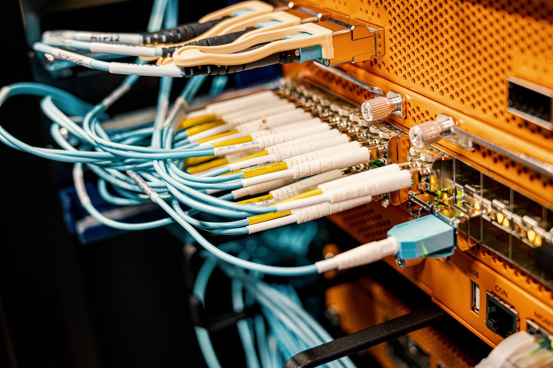
The short answer
Single mode OS2 fiber has a core of roughly 9 microns and carries light from a 1310 or 1550 nm laser over distances measured in kilometers. Multimode OM3, OM4 and OM5 have a 50 micron core and use cheaper 850 nm optics, but reach is the constraint: OM3 supports 10 Gb/s to 300 m, OM4 to 400 m, and OS2 to 10 km and beyond. Specify OS2 between buildings and for any backbone that may carry 40 or 100 Gb/s later. OM4 remains a reasonable choice for an in building riser where the longest run is a few hundred meters and the port count makes the optics price difference worth having.
| Core size | OS2 about 9 microns, OM3 to OM5 50 microns |
|---|---|
| 10 Gb/s reach | OM3 300 m, OM4 400 m, OS2 10 km and beyond |
| Loss budget inputs | 0.75 dB per connector pair, 0.3 dB per splice |
| Standard | ANSI/TIA-568.3-D optical fiber cabling |
| Testing | Tier 1 OLTS loss, Tier 2 OTDR trace per strand |
| License | CSLB #472017, C-7 Low Voltage Systems |
Which fiber to specify, and when the answer changes#
Between buildings, specify single mode OS2. Inside a building, OM4 multimode or OS2 both work for runs of a few hundred meters, and the choice comes down to how many optics you will buy and how long the cable stays in the wall. Any backbone that may carry 40 or 100 Gb/s on a duplex pair later should be OS2.
That is the answer. Three inputs drive it: the distance of the longest link, the optics your switches will use over the life of the cable, and how many years the cable will be in place before anyone can practically replace it. Distance is knowable from the drawings. Optics are a forecast. Service life is the input owners underestimate, because a backbone installed in a riser during a renovation is not coming back out until the next renovation.
Telelink Business Services is a licensed C-7 Low Voltage Systems Contractor, CSLB License #472017. Our fiber optic cabling page covers the installation scope; this guide covers the specification decision.
Core size and the physical difference#
The difference is the glass, and specifically the diameter of the core the light travels in.
Single mode fiber has a core of roughly 9 microns. That is narrow enough that light travels essentially one path down the fiber. There is no spreading of the pulse caused by different paths arriving at different times, so the distance a given data rate can travel is limited by attenuation and by the properties of the laser rather than by the fiber’s geometry. Single mode uses 1310 nm and 1550 nm sources.
Multimode fiber has a 50 micron core. Light enters at many angles and travels many paths, or modes, at once. Paths that bounce more arrive later, which spreads the pulse and eventually blurs one bit into the next. That effect, modal dispersion, is what caps multimode distance, and it gets worse as the data rate rises. OM3, OM4 and OM5 are laser optimized fibers with a refractive index profile designed to reduce it, paired with 850 nm vertical cavity surface emitting lasers.
Two practical consequences follow from the core size. Alignment tolerance on a single mode splice or connector is tighter, which is why single mode field termination is less forgiving and why fusion splicing is the normal answer. And a multimode link’s distance limit moves every time the data rate changes, while a single mode link’s usually does not.
Legacy 62.5 micron OM1 still exists in older buildings, often alongside early 50 micron OM2, which shares the OM3 to OM5 core size but is not laser optimized and reaches far less at 10 Gb/s. Do not extend either one. Match them only long enough to plan their replacement, and calculate the loss budget for any mixed path separately.
Reach by fiber type: OS2, OM3, OM4 and OM5#
| Fiber | Core | Wavelength | 10 Gb/s reach | Higher speeds | Typical use |
|---|---|---|---|---|---|
| OM3 | 50 µm | 850 nm | 300 m | 40 and 100 Gb/s over parallel fiber, shorter reach | Extending an existing OM3 plant |
| OM4 | 50 µm | 850 nm | 400 m | 40 and 100 Gb/s over parallel fiber, shorter reach | New in building riser backbones |
| OM5 | 50 µm | 850 to 950 nm | 400 m | Short wavelength division multiplexing on duplex fiber | In building where duplex fiber must scale past 10 Gb/s |
| OS2 | 9 µm | 1310 and 1550 nm | 10 km and beyond | 40 and 100 Gb/s on duplex fiber without parallel optics | Campus links, carrier entrance, any future high speed backbone |
The row that decides most specs is the last column of the OS2 line. Moving a multimode backbone past 10 Gb/s generally means parallel optics, which use four or eight fibers in each direction instead of one, so the strand count of the link multiplies. On OS2 the same duplex pair carries the higher speed and only the transceiver changes. That is the argument for OS2 on anything you expect to upgrade rather than replace.
Optics cost, and how the gap has narrowed#
The historical case for multimode was the transceiver. An 850 nm VCSEL was substantially cheaper to make than a 1310 nm laser, and on a backbone with many links that difference added up.
Two things changed. Single mode optics for short reach applications became much cheaper as volume grew in large data center deployments. And the multimode path to higher speeds started requiring parallel optics and MPO infrastructure, which added cost back on the cabling side.
The way to evaluate this on a real project is to price the whole link, not the transceiver. A link costs: the cable, the pathway, the terminations, the enclosure hardware, the testing, and two transceivers per link per generation of switch. On a four link riser backbone the transceiver delta over the cable’s life is small against the cabling cost, and OS2 is easy to justify. On a floor of a data center or server room with hundreds of short links, the transceiver count dominates and multimode remains the cheaper build. Between those two cases, price both and let the owner choose with the numbers in front of them.
Strand count and proving the link on paper#
Two planning habits save more money than the fiber type choice does.
The first is strand count. Pull twelve where four are needed. The cable costs somewhat more per foot and the labor is nearly identical, because the crew, the pathway, the pull and the enclosure work are the same whether the sheath holds four fibers or twelve. What that buys is the ability to add a switch stack, a camera head end, a building automation network or a carrier handoff without a second pull into an occupied conduit. Campus links between buildings often warrant 24 strands or more, because the conduit between two buildings is the hardest one to get back into. On the Touro University campus building renovation in Vallejo, the fiber backbone tied the new IT rooms together and connected the building to the campus network, on a campus that will be in use for decades. Strand count on a link like that is planning for switch generations nobody has specified yet.
The second is the loss budget. Every link gets calculated before cable is ordered. The calculation adds the cable attenuation over the length, the maximum loss per mated connector pair (0.75 dB in ANSI/TIA-568.3-D), and the maximum loss per splice (0.3 dB), then compares the total against the channel insertion loss the optics allow.
Here is the same 400 m link priced two ways. Assumptions: fusion splice to factory pigtails at each end, so two splices, and one mated connector pair at each patch panel, so two connector pairs. The attenuation coefficients below are the maximum values ANSI/TIA-568.3-D allows for the cable type: 3.5 dB/km at 850 nm for 50 micron multimode, and for single mode 1.0 dB/km at 1310 nm inside plant and 0.5 dB/km outside plant, the outside plant figure applying here because the campus link leaves the building. A typical manufacturer data sheet is better than the standard’s ceiling, often near 3.0 dB/km at 850 nm and 0.4 dB/km at 1310 nm, but a budget built on the maximum is the one that still holds when the cable actually delivered sits at the limit.
| Element | OM4 riser link, 400 m | OS2 campus link, 400 m |
|---|---|---|
| Attenuation coefficient, TIA maximum | 3.5 dB/km at 850 nm | 0.5 dB/km at 1310 nm, outside plant |
| Cable loss over 0.4 km | 1.40 dB | 0.20 dB |
| Two mated connector pairs at 0.75 dB | 1.50 dB | 1.50 dB |
| Two fusion splices at 0.30 dB | 0.60 dB | 0.60 dB |
| Calculated link loss | 3.50 dB | 2.30 dB |
| Channel allowance at 10 Gb/s | 2.9 dB, 10GBASE-SR on OM4 | 6.2 dB, 10GBASE-LR per IEEE 802.3 Clause 52 |
| Result | Does not close | Closes with 3.90 dB of margin |
Read that table carefully, because it is the argument in one place. Using the standard’s maximum values, an OM4 link at its published 400 m reach does not close once you add two connector pairs and two splices. It can be made to work with fewer connection points, or with connectors that measure well below the 0.75 dB maximum, or by shortening the run. The single mode version of the same link closes with several decibels to spare and would still close with more connections and more length. This is why the budget is calculated on paper before anyone orders cable, and why a design that assumes the published reach figure without counting connections is a design that fails at test.
Termination, connectors and MPO polarity#
Three termination methods show up on commercial work, and the specification should say which one it wants.
Fusion splicing to factory terminated pigtails. The cable strands are fusion spliced to pigtails with factory polished connectors and the splices are protected in a tray inside the enclosure. This gives the lowest and most consistent loss per termination and is the normal choice for backbone and outside plant.
Pre terminated MPO trunks. The cable is manufactured to length with connectors on both ends, usually MPO carrying 12 or 24 fibers, landing in cassettes that break out to LC duplex. Installation is fast and the loss is predictable, but the length has to be right and the pathway has to accept the pulling grip and the connector bundle. Measure the route, including every vertical rise and every slack loop, before ordering.
Field polished or mechanical connectors. Appropriate for small counts and repairs. Loss is higher and more variable than a fusion splice, so they are a poor choice for anything permanent on a backbone.
Connector types are LC, SC and MPO. LC duplex is the standard on current switches and patch panels. SC appears on older equipment and some carrier handoffs. MPO carries parallel optics and high density trunks.
MPO brings one planning item that copper does not have: polarity. The connector carries a whole row of fibers, and transmit at one end has to land on receive at the other for every pair in the bundle. TIA describes three connectivity methods for doing that, using different combinations of trunk type, cassette and patch cord. They are not interchangeable. Pick one method for the whole system, write it on the drawings, and use the cords that method requires, because mixing methods produces links that fail polarity verification and get diagnosed as broken cable. MPO also comes pinned and unpinned, and a pinned connector mated to another pinned connector will not seat correctly.
Tier 1 and Tier 2 testing on the backbone#
Every strand gets tested, and the tier should be named in the spec.
Tier 1 uses an optical loss test set to measure insertion loss end to end on each strand, at the wavelengths the strand will carry: 850 and 1300 nm for multimode, 1310 and 1550 nm for single mode. It records length and verifies polarity. The measured loss is compared against the calculated budget for that link, which is the same calculation shown above, and every strand has to pass.
Tier 2 adds an OTDR trace of each strand. The trace shows every connector, splice and bend as an event along the length, so a link that passes total loss while hiding a marginal splice is caught before turnover. Tier 2 is also the baseline record that makes locating a future break a measurement instead of a search.
Both tiers depend on connector cleanliness. End faces get inspected and cleaned before every mating, including on the reference cords, because a single contaminated end face can add more loss than every splice in the link combined. Results are delivered per strand in the tester’s native format and as PDF, with labels matching the enclosure and the drawing. Our cabling testing and audits page covers how we test plant we did not install, and our network room buildout page covers the enclosures the fiber lands in.
Next step#
Send the backbone riser diagram, the campus site plan, or the fiber section of your Division 27 specification through request a bid. We will return a design with fiber type, strand count, termination method and testing tier, a loss budget for every link, and OS2 and OM4 priced side by side where the spec leaves the choice open. If the question is how to get the cable between two buildings in the first place, our guide on fiber trench versus wireless bridge covers that decision.
This article is general information for planning and specification, not a bid, engineering advice or legal advice. Codes and standards change; confirm the current edition with the authority having jurisdiction. Scope and price for a specific building come only in a written proposal.