The short answer
An MDF is a building's main telecommunications room, where the service entrance, core switches and backbone originate; an IDF is a floor or wing room that serves the horizontal cabling in its area and connects back to the MDF. A building needs at least one telecommunications room per floor, and another wherever a horizontal run would otherwise exceed the 90 meter permanent link limit. Each room needs dedicated space with no water or mechanical equipment passing through it, racks with clear working space front and back, dedicated electrical circuits, a bonding conductor to the building service ground, continuous cooling, and labeling to ANSI/TIA-606. Certification results and as-built rack elevations are delivered at closeout.
| Spaces and pathways | ANSI/TIA-569 |
|---|---|
| Bonding and grounding | ANSI/TIA-607 |
| Labeling and records | ANSI/TIA-606 |
| Cabling | ANSI/TIA-568.2-E copper, 568.3-D fiber |
| Electrical handoff | Circuits and bonding conductor to service ground by C-10 |
| Project examples | State Controller's Office, Touro University |
Locating and sizing the room to TIA-569#
The room is the foundation of the cabling system, and it is often assigned the floor space left after the other trades are laid out. ANSI/TIA-569 is the standard for telecommunications pathways and spaces. Provide at least one telecommunications room per floor. Add rooms where the horizontal run to any outlet would exceed the 90 meter permanent link limit or where the served floor area becomes large; the standard sizes rooms by the floor area they serve, so confirm the required dimensions against the current edition for the area your room covers. Stack the rooms vertically so the backbone runs straight.
Location rules matter more than square footage. The room should be a dedicated space, not shared with electrical panels, mechanical equipment or storage. No water, drain or sprinkler main should pass through it; where sprinklers are required, ask for a drip pan or a cage over the racks. Keep it away from transformers, motors and other sources of electromagnetic interference. Provide a door at least 36 inches wide that opens outward with no sill, a clear ceiling height of at least 8 feet, and lighting bright enough to read a label at the back of a rack. Fire-retardant plywood backboards on at least two walls provide mounting for the service provider demarcation, the busbars and wall-mounted equipment.
On the State Controller’s Office tenant improvement in Sacramento, the network room was built out on a working state agency floor to serve new cabling and surveillance, and the room location and pathway to the building backbone were settled before any cable was ordered. That order of operations is the point of this guide.
Racks, cabinets, ladder rack and tray#
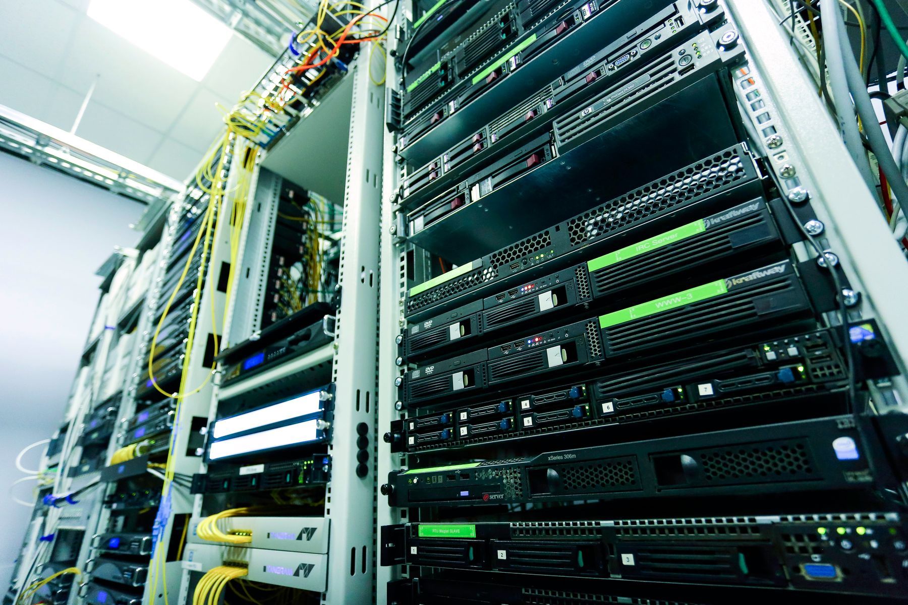
The rack count follows the port count. A 45 rack unit two-post rack holds patch panels for a few hundred horizontal drops plus the switches that serve them, with horizontal and vertical managers between. Plan the layout so patch panels and switches alternate or sit in adjacent racks with a manager between, so no patch cord crosses the room. Leave at least 36 inches of clear working space in front of and behind every rack, and one rack’s worth of floor space empty for growth.
Two-post racks are the default in a dedicated room. Four-post racks carry heavy equipment, servers and UPS units. Cabinets add lockable doors and contained airflow at the cost of floor space, money and access; they belong in shared rooms and anywhere equipment needs to be locked away from people who have a key to the room. Whatever the choice, anchor to the floor per the manufacturer and the structural requirements; in California that means seismic anchoring detailed on the drawings.
Overhead ladder rack runs from the room entrance over the racks and drops cable into the vertical managers. It is bonded, sized for the cable count with room to grow, and supported from the wall and the racks rather than the ceiling grid. Where cable enters from the corridor, sleeves or a tray penetrate the wall with firestopping in a listed system. The pathway from the room to the horizontal distribution (tray, J-hooks, conduit) is sized to TIA-569 fill guidance and shown on the drawings so it is priced.
Power: dedicated circuits, receptacles and UPS#
Power is electrical scope. What the low voltage contractor does is state the requirement clearly and early: how many dedicated circuits, at what amperage, where the receptacles go, and whether any equipment needs a specific receptacle type. A typical IDF gets at least two dedicated 20 A circuits on separate breakers with receptacles at each rack; the MDF gets more, plus whatever the UPS and service provider equipment require. Convenience outlets on the wall for a laptop and a tester are worth asking for.
The UPS is usually in the low voltage contract and sized by the connected load with a runtime target agreed with the owner. Runtime is a policy question: long enough to ride through a blip and shut down cleanly, or long enough to keep the phones and access control working through an outage. Network-connected UPS units report battery status to IT and should be on the management VLAN. PoE has raised rack power draw substantially, and a switch full of 802.3bt ports for cameras and access points belongs in the load calculation.
The handoff is documented on the shop drawings: receptacle locations by rack, circuit numbers once the electrician assigns them, and the UPS location. Telelink Business Services is a licensed C-7 Low Voltage Systems Contractor, CSLB License #472017. The dedicated circuits, receptacles and panel work are performed by the project’s C-10 electrical contractor.
Cooling and airflow for a small room with a big heat load#
A rack of PoE switches and a UPS produces a concentrated heat load, in a room that is often left off the building HVAC schedule. The requirement is continuous cooling, 24 hours a day, independent of the occupied schedule, with temperature and humidity held in the ranges the equipment manufacturers publish. A dedicated split system is the usual answer for an MDF; a transfer fan or a dedicated supply and return may suffice for a small IDF, and the mechanical engineer decides. What the low voltage contractor provides is the heat load: equipment watts by rack, with growth.
Inside the room, airflow follows the equipment. Switches typically draw air from the port side or the side and exhaust at the back; arrange racks so the exhaust of one is not the intake of the next. Blank panels close empty rack units so cooled air passes through equipment, not around it. A networked temperature sensor reporting to IT is inexpensive and alerts before equipment shuts down.
Bonding and grounding to TIA-607: who does what#
ANSI/TIA-607 is the standard for telecommunications bonding and grounding. Its purpose is to keep every rack, cabinet, tray, ladder rack, shield and busbar at the same potential and connected to the building’s grounding electrode system, so that faults, surges and static have a low-impedance path that is not through the equipment or the technician.
The components, in current TIA-607 terminology, are the primary bonding busbar (PBB) in the MDF or entrance facility, a secondary bonding busbar (SBB) in each IDF, a telecommunications bonding backbone (TBB) connecting the PBB to every SBB, and rack bonding conductors from each rack, cabinet and ladder rack section to the busbar in that room. Larger racks get a rack bonding busbar. Conductors are copper, sized per the standard, labeled, and run as directly as possible.
The scope split is the same on every project. The electrical contractor bonds the PBB to the building electrical service ground with the telecommunications bonding conductor; that connection ties the telecommunications bonding system to the building grounding electrode system, and it is electrical scope. Telelink provides and installs the busbars, the bonding backbone between rooms, the rack and ladder rack bonding and the labeling, and shows the handoff on the shop drawings. Paint is removed under every lug or thread-forming hardware is used, because paint is an insulator and a lug tightened over it does not make electrical contact. Our network room buildout page states this split in its scope note.
Cable management, labeling to TIA-606 and patching standards#
Cable management decisions made at rough-in determine how the room works for the rest of its life. Horizontal cable enters the rack from the top through the ladder rack, drops into the vertical manager, and is dressed into the back of the patch panels with bend radius respected and bundles supported, never hanging from the terminations. Use hook-and-loop straps rather than cable ties on any bundle that will be opened again, and leave service loops in the ceiling rather than in the rack.
ANSI/TIA-606 is the administration standard. It defines identifiers for every space, pathway, cable, termination and bonding component, and requires that the labels match the records. The scheme (room, rack, panel, port, and the outlet identifier at the far end) is submitted for approval before the first label is printed, because changing a scheme after termination means relabeling everything. Labels are machine-printed on materials rated for the environment, applied at both ends of every cable, on every patch panel port, on every rack and on the busbars.
Patching follows a written standard so any technician can trace a connection. Patch cords are sized to the run with no slack loops, routed through the managers, and color coded by function where the owner wants it. Fiber is terminated in enclosures with strands labeled and the polarity method recorded. The Cat6 vs Cat6A guide covers the choice of horizontal cable and why Cat6A’s larger diameter changes the pathway and manager sizing in the room.
Testing, certification and as-builts#
Every horizontal permanent link is certified with a calibrated field tester at the level the category requires, and every fiber link is tested for loss with an optical loss test set; an OTDR trace is added where the specification or the owner wants it. Failed links are reworked and retested before turnover. Results are delivered in the tester’s native format and as PDF, organized by room and panel to match the labels.
The as-built package makes the room maintainable: rack elevations as built, patch panel and cable schedules, the floor plan with outlet identifiers, the riser diagram with backbone routes and counts, the bonding diagram with the electrical handoff point, photographs of the finished room, and a record of spare capacity in racks, pathways, panels and fiber strands. On the Touro University renovation in Vallejo the room buildout, fiber backbone and wireless cabling were documented this way so campus IT could operate and extend the rooms without a return visit. Our structured cabling and fiber optic cabling pages describe the testing in more detail.
The network room checklist#
Use the table when reviewing a room design or walking a finished room before turnover.
| Item | Requirement | Whose scope |
|---|---|---|
| Location | Dedicated, stacked, no water or drains, away from EMI, one per floor minimum | Architect, engineer |
| Size and clearances | Sized to served area per TIA-569; 36 inch clearances; room to grow | Architect |
| Door, ceiling, backboard | 36 inch outward door, no sill; 8 foot clear ceiling; fire-retardant plywood | GC |
| Pathway in and out | Sleeves or tray with listed firestopping; tray, J-hooks or conduit sized to fill | Division 27 (state it) |
| Racks and anchoring | Two-post, four-post or cabinet per use; seismic anchoring detailed | Division 27 |
| Ladder rack | Over racks, bonded, wall and rack supported | Division 27 |
| Dedicated circuits | Count and amperage per load; receptacles at each rack | C-10 electrical |
| UPS | Sized to load and runtime policy; on management VLAN | Division 27 |
| Cooling | Continuous, independent of building schedule; heat load provided | Mechanical engineer |
| Bonding to service ground | Telecommunications bonding conductor from PBB to electrical service ground | C-10 electrical |
| Busbars, backbone, rack bonding | PBB, SBBs, TBB, rack bonding conductors per TIA-607 | Division 27 |
| Labeling | TIA-606 scheme submitted and approved; both ends, every port, every rack | Division 27 |
| Certification | Copper permanent link and fiber loss testing; results by panel | Division 27 |
| As-builts | Elevations, schedules, plans, riser, bonding diagram, photos, spares | Division 27 |
| Environmental monitoring | Temperature sensor and UPS on network, reporting to IT | Division 27 or owner |
Next step#
If you are planning an MDF or IDF for a new building, a tenant improvement or a campus renovation, request a bid with floor plans and drop counts and we will return a room-by-room scope with the electrical and mechanical handoffs marked. General contractors coordinating the Division 26 and 27 split can find our standard scope language on the for general contractors page.
This article is general information for planning and specification, not a bid, engineering advice or legal advice. Codes and standards change; confirm the current edition with the authority having jurisdiction. Scope and price for a specific building come only in a written proposal.